audio emotion toy #
A guide to create an enclosure for a simple python audio program for Raspberry Pi Zero that will play random sounds from different folders depending on the button you press
project goal #
The initial goal of the project is to provide a simple project that will teach basics of enclosures, LEDs and buttons, soldering, python, and raspberry pi. The pros of the approach I’ve taken is that you can create this project using minimal equipment and watercolour paper, not requiring you to do any woodworking or 3d printing for the enclosure. The goal of the project itself beyond education is to create a small box that will play short sound clips which will have 4 different folders with different categories of sound files (wav, mp3, etc)
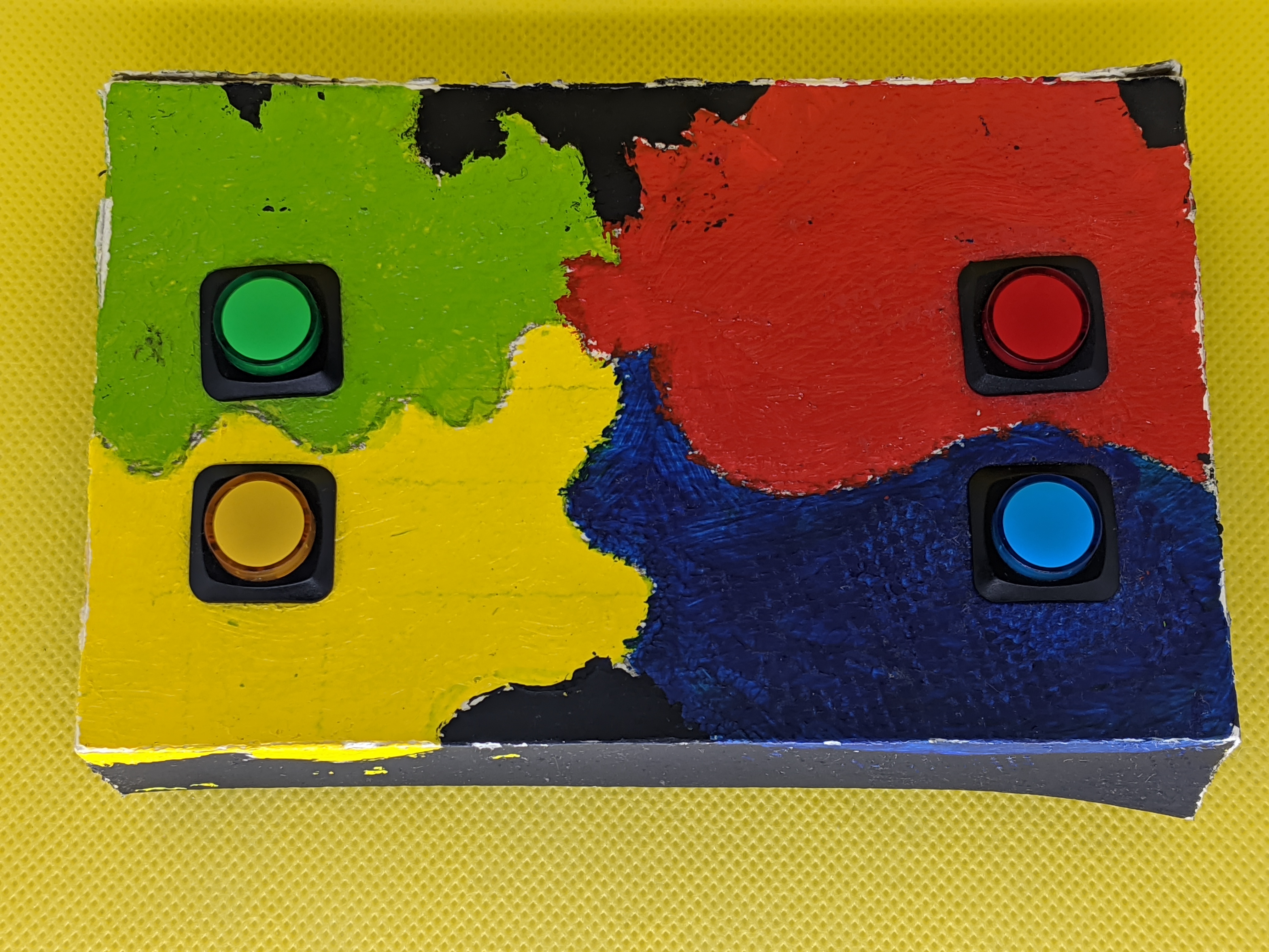
In the current design, the setup is to have each color correspond to a different emotion:
GREEN = FEAR
RED = ANGRY
YELLOW = HAPPY
BLUE = SAD
This could then be used to spend time with children or anyone else who has challenges or interest in recognizing emotions and trying out the different sounds, and discussing if you think they correspond to the emotion label, and why or why not.
I also think its a fun concept! Future stretch goals may include:
- attempts to use machine learning and/or large datasets to provide more audio clips beyond the samples I’m providing here.
- 3d printed enclosure for a more sturdy design
parts list #
I purchased all parts from Adafruit. You could also find cheaper vendors for the same. I reccomend Adafruit especially for people in the early stages of learning, due to better documentation, reliability of parts, and fast shipping in the US. Howver you can save a lot of money using other vendors such as Mouserr or Aliexpress.
Raspberry Pi Zero W
Adafruit I2S 3W Stereo Speaker Bonnet for Raspberry Pi - Mini Kit
Stereo Enclosed Speaker Set - 3W 4 Ohm - we will only be using one of the 2 included speakers
Watercolour paper or any other thick stock paper that you can fold around the house, at least 7.5’’ x 13’’ size
16mm Illuminated Pushbutton - Yellow Momentary
16mm Illuminated Pushbutton - Red Momentary
16mm Illuminated Pushbutton - Green Momentary
16mm Illuminated Pushbutton - Blue Momentary
Double-Side Prototype PCB Board
Optional:
Small Alligator Clip Test Lead (set of 12) not required but helpful for testing parts
Anker PowerCore 10000 Portable Charger if you want to make the project portable, otherwise use official RPi power supply
Solder wick - 3S 5ft. not required but super helpful for cleaning up any messy soldering or soldering mistakes
You will also need
- Soldering gun - for example Weller WLC100 40-Watt Soldering Station
- Solder - for example Mini Solder spool
- Wiring - for example Stranded-Core Wire Spool - 25ft - 22AWG - Red
- Watercolour paper or other thick stock paper that will provide some durability. Printer paper will not be thick enough for this project. Feel free to get creative in making your enclosure!
bonnet notes #
this guide assumes you already have a raspberry pi zero with raspbian setup and male headers attached - the speaker bonnet uses female headers
learning guide - Adafruit Speaker Bonnet for Raspberry Pi
- note that pins 18, 19, and 21 of the pi are used by the sound bonnet, you cannot use them for any other purpose
- 3V and 5V and GND at the ’top’ of the GPIO are also used by the bonnet
- if you are a beginner, I’d follow the guide step by step and get through the testing portion of the pushbutton before you solder this together. If you’re experienced and confident in what you’re doing, you can skip the testing wiring section
enclosure and testing wiring #
watercolour paper enclosure #
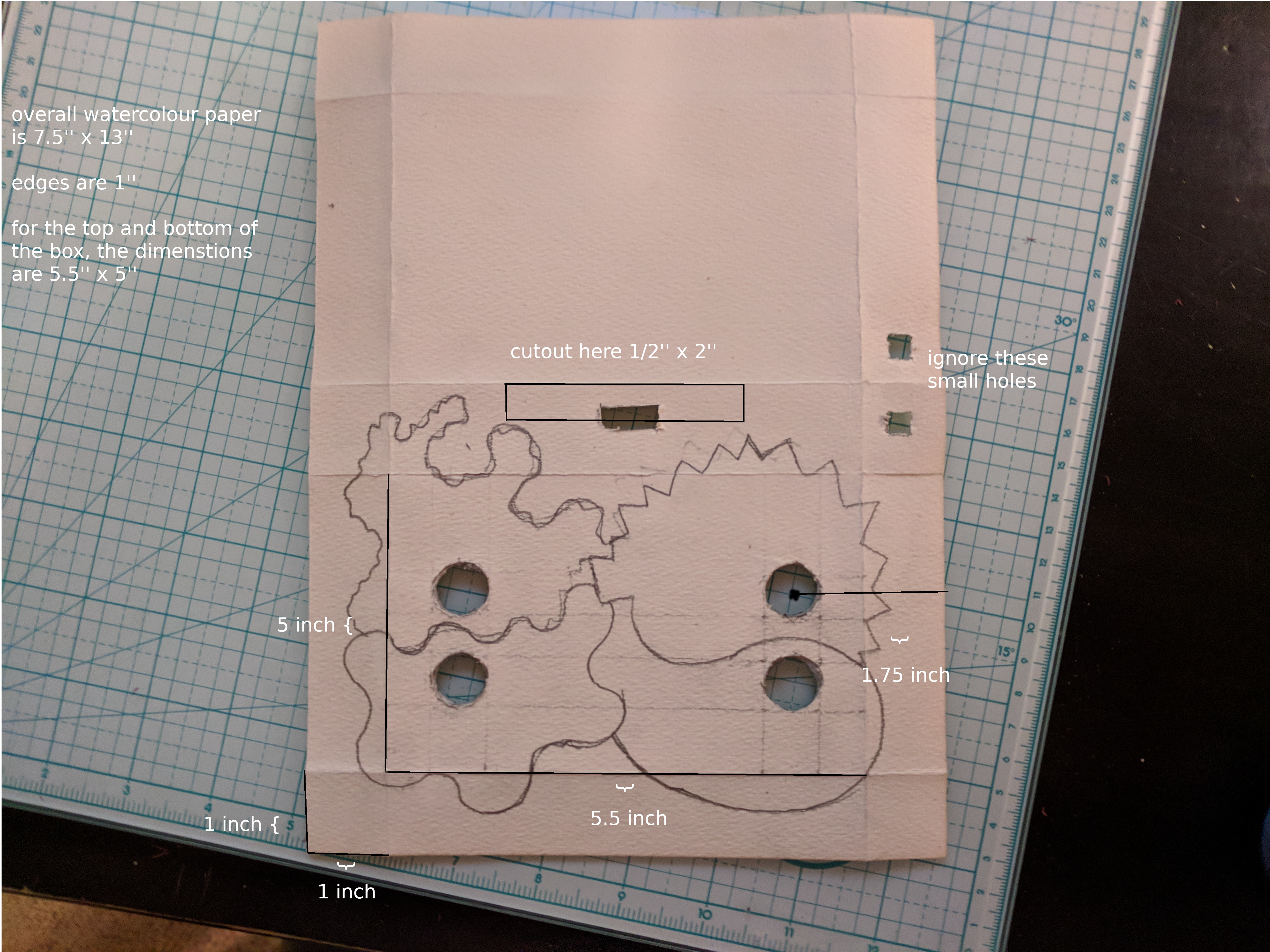
The box enclosure is made using this origami video watch this for the step by step box creation instructions See the below reference image for watercolour paper size that I used, the first step will be to cut your paper to 7.5’’ x 13’’ then read notes below and watch origami video
- note the cutout is marked as I neglected to make it big enough when I was originally making this
- you may want to place your raspberry pi over the paper and visually verify the length of the space from the hdmi port to the power/usb ports
- if you’re unsure of this step you can always go back and do it after you’ve assembled the box
- the spacing for the buttons (1.75’’) from left and right sides is important so that the box can open and close properly, to leave space for other components. The vertical placement of them is not that important.
- for the size of the holes, place the led/button ring (remove the holder ring) where you want the buttons, then use a pencil to mark the inside of the ring, and cut out that hole. You may want to test this on a seperate paper before trying it out on your enclosure
- once you’ve made all the needed cuts, and drawn out your intended design go ahead and paint the box with acrylics before you fold and glue the box together. I used 4 sections for 4 different colors / emotion categories.
- you can use glue sticks and some crazy glue/gorilla glue to get the box to hold per the video above
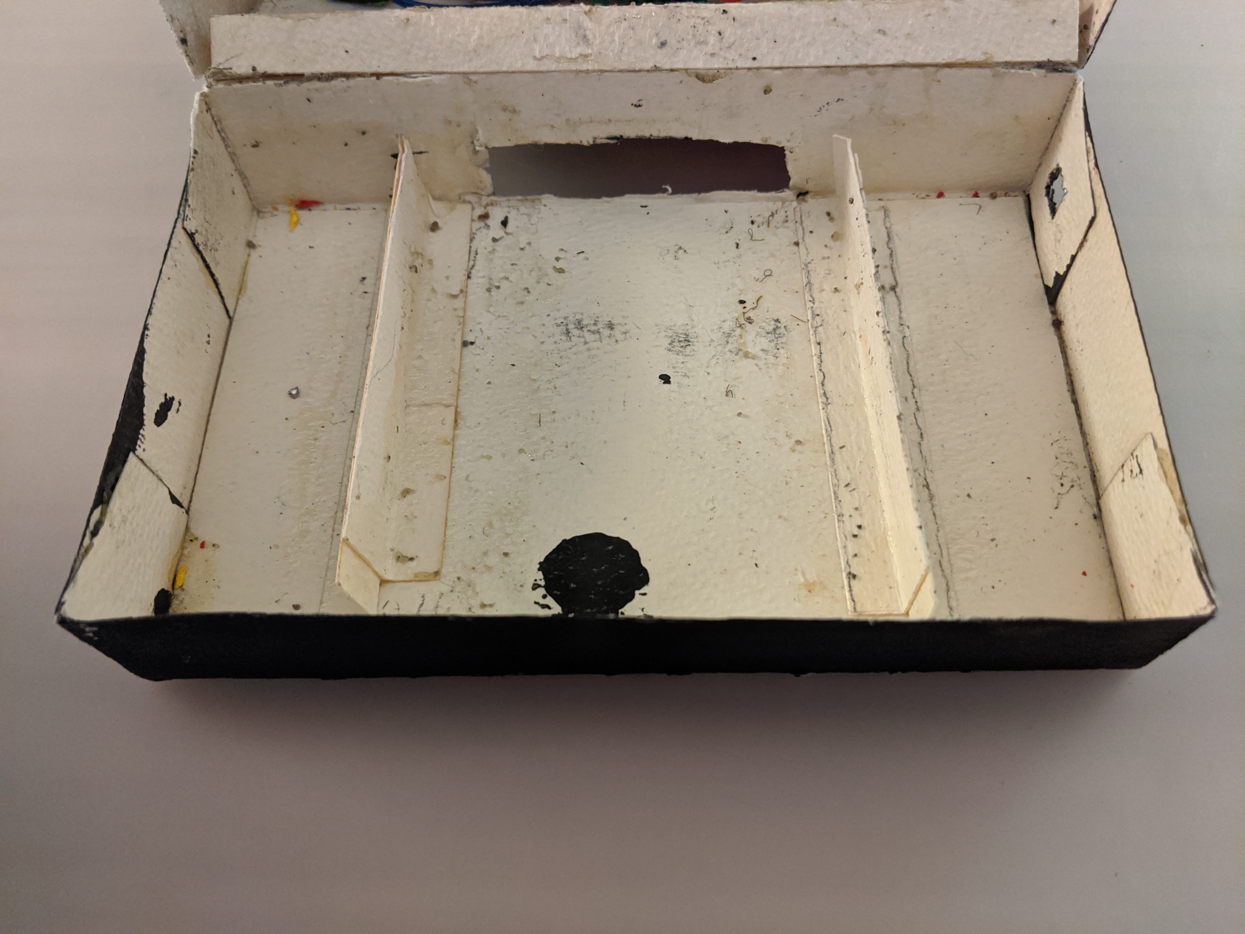
Once you’ve gotten the box setup and folded and glued together, there’s a few more steps to finish the box
- create little “tabs” that will hold the raspberry pi zero and spaeker in place. Refer to photo below. These are the height of the box 5’’ x 1-1.25’’ and I fold them down next to each other and glued it together. Not the prettiest approach but it works. You don’t want the tabs too tall because the wires need to be able to go over them.
- Alternatively, if you have screws that fit the mounting holes for Raspberry pi and the speaker, you can just mount directly to the bottom of box, and skip the tabs.
- I also created a 5.5’’ tab to help protect the corner where the box opens and closes
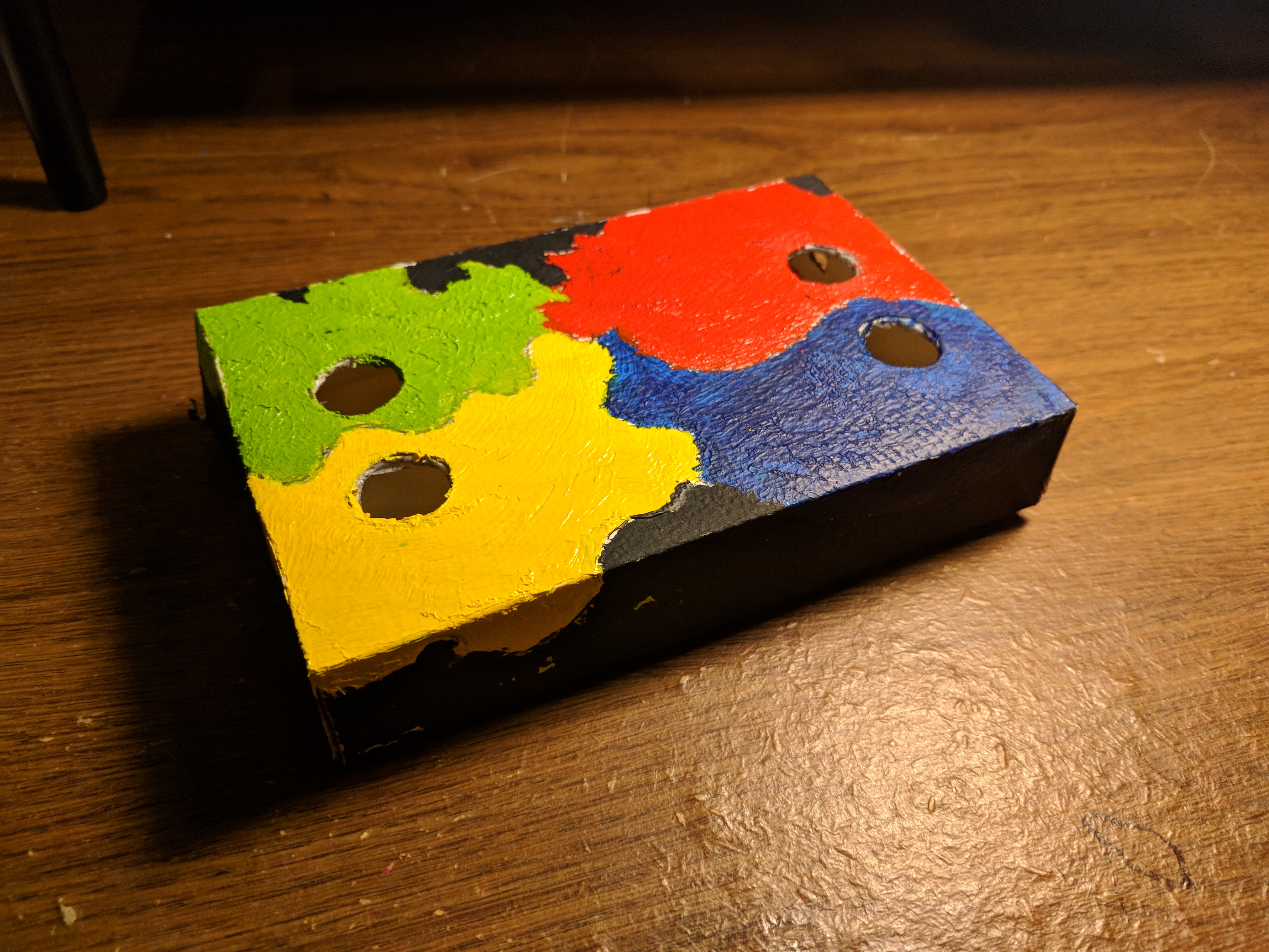
- the photo below is of the box over 2 years after I created it. It definitely looks a bit messy from all the glue and tinkering, however the box has held up well, I’ve carried it in my backpack, etc.
- Reference image for after its all painted and glued and the box is closed
testing wiring #
To make things simple, we will only be testing a pushbutton directly to the Pi, we will not be testing the speaker bonnet. This is not a necessary step but will help you ensure that at least one of your buttons is working and help you understand how it works.
For a reference on Raspberry Pi GPIO please see the official reference here
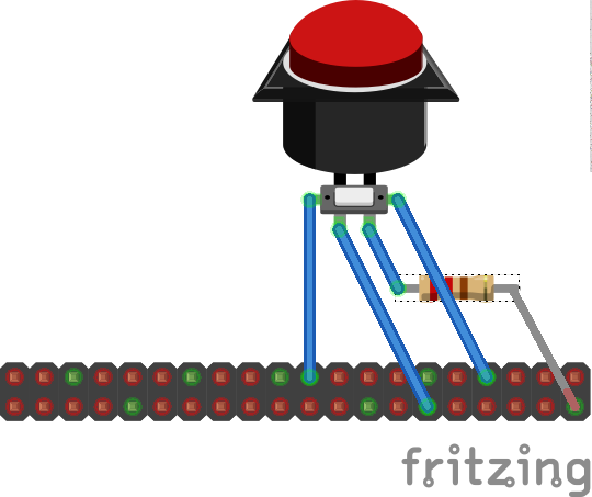
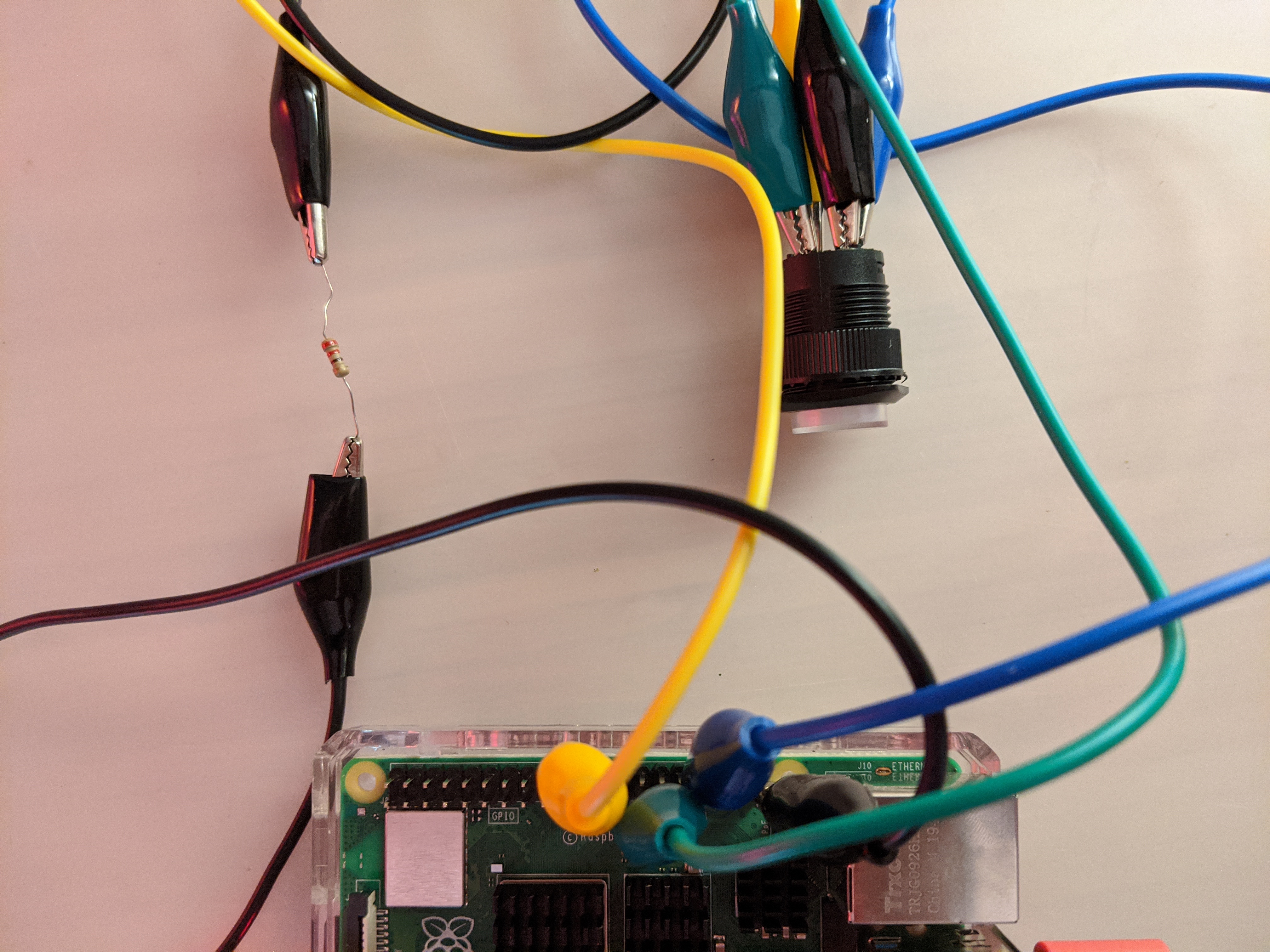
Let’s try testing with just one (for example, green) momentary illuminated pushbutton. For each pushbutton, there are 2 sets of contacts, one for the led and one for the button. Per the product page linked above ‘There are two contacts for the button and two contacts for the LED, one marked + and one -’ and the contacts that are not labeled with + or - are for the button parts. I tested this with alligator clips, but I’m sure you could find another way to test this. I’ll walk through testing just the green pushbutton, but you could use the same procedure to test all of them, as long as you’re using a valid GPIO pin. Keep in mind I’m using the BCM scheme and you can double check your specific BCM mapping using the “pinout” command on the Raspberry Pi terminal. Would also reccomend you take a look at the offiical RPi GPIO documentation for reference
- RPi GPIO 5 to + (positive) contact on green momentary pushbutton
- 220 to 1000 ohm resistor on the - (negative) then connect back to ground pin on RPi (I used a 220 ohm resistor)
- RPi GPIO 25 to one side of the button contacts
- RPi ground to the other side of the button contacts
- in the diagram, the leads connecting directly to pushbutton are the LED, and the leads going out to the side are for the button part.
Additional reference images show green alligator clip on the positive LED contact and black on the negative -> resistor -> ground, and yellow on going to 25 and blue going to ground. This is using a Raspberry Pi 4 for testing purposes however this is an identical setup to a Raspberry Pi Zero with male headers.
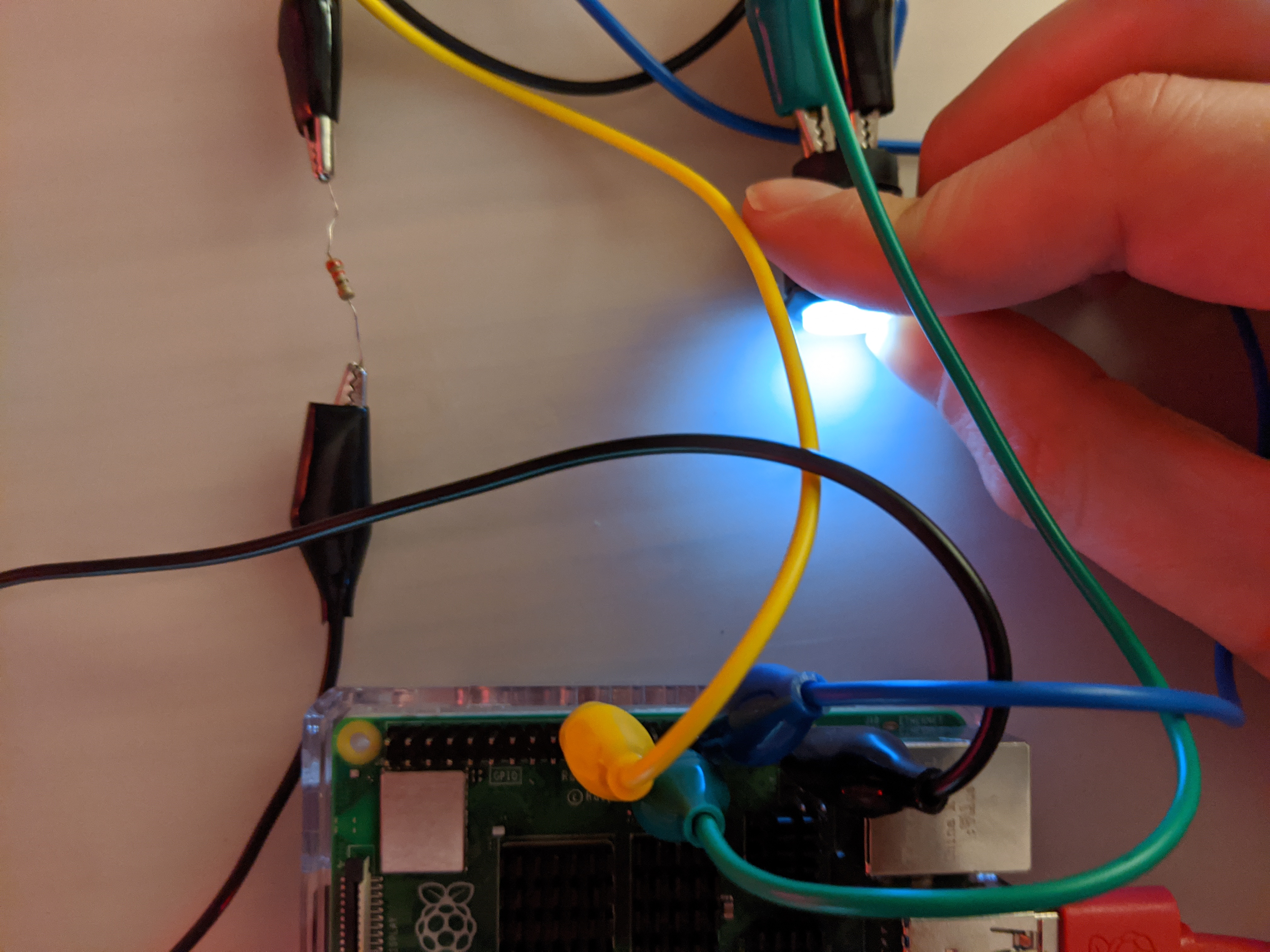
It works!
testing python script #
first you should run this command to ensure you have the needed packages
# sudo apt-get install python-rpi.gpio python3-rpi.gpio
You can use this script (in the repository as test.py) to test. If you can ssh to your raspberry pi, you can copy/paste the script onto the Pi. Or you can use scp. Or you could access the desktop with HDMI and manually write the script.
import time
import RPi.GPIO as GPIO
GPIO.setmode(GPIO.BCM)

GPIO.setup(25, GPIO.IN, pull_up_down=GPIO.PUD_UP) #GREEN B = FEAR
GPIO.setup(5, GPIO.OUT) #GREEN L = FEAR

try:
    while True:
        button_state = GPIO.input(25)
        if button_state == False:
            GPIO.output(5, True)
            print('Button Pressed....')
            time.sleep(0.2)
        else:
            GPIO.output(5, False)
    except:
        GPIO.cleanup()
Once you have the script in place on your RPi, make the script executable and run it!
# sudo chmod +x test.py
# python test.py
If you are not able to get this to work - stop. Re-read relevant documentation. Ensure that you have the wiring done correctly and there is no error thrown when you run the python script. Feel free to submit an issue on the repo for any questions or concerns on these instructions. If this test isn’t working, you do not want to proceed to soldering.
Assembly #
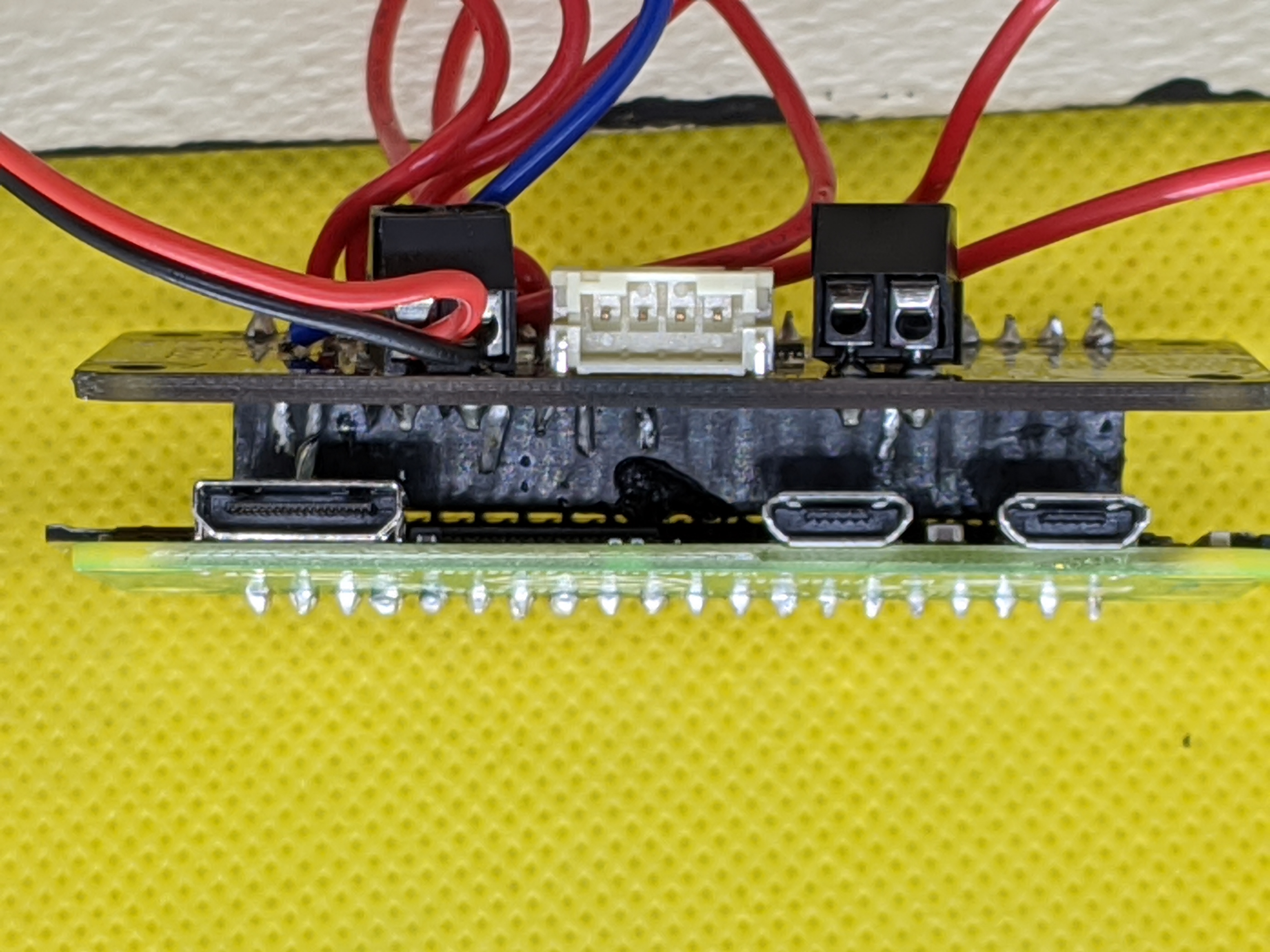
Ok, now we will put the parts together in the box. This is going to take a fair bit of tinkering. You’ll want to go back to the above ‘overview of parts’ section and see the documentation for the speaker bonnet. You could solder the GPIO pins to the bonnet before you attach it to the Pi or, you could attach it to the Pi first. If you attached the speaker bonnet first, as I did, you’ll need to solder on the underside of the bonnet. I found this somewhat infuriating but was able to do it with using a decent bit of exposed wire and a lot of patience. If you tried soldering the GPIO connections on the bonnet first before connecting it to the Pi and soldering that, please let me know if you found that easier.
Either way, just ensure the bonnet will be able to connect and sit as intended. I would not advise attaching the speaker itself until the wiring to the pushbuttons is done.
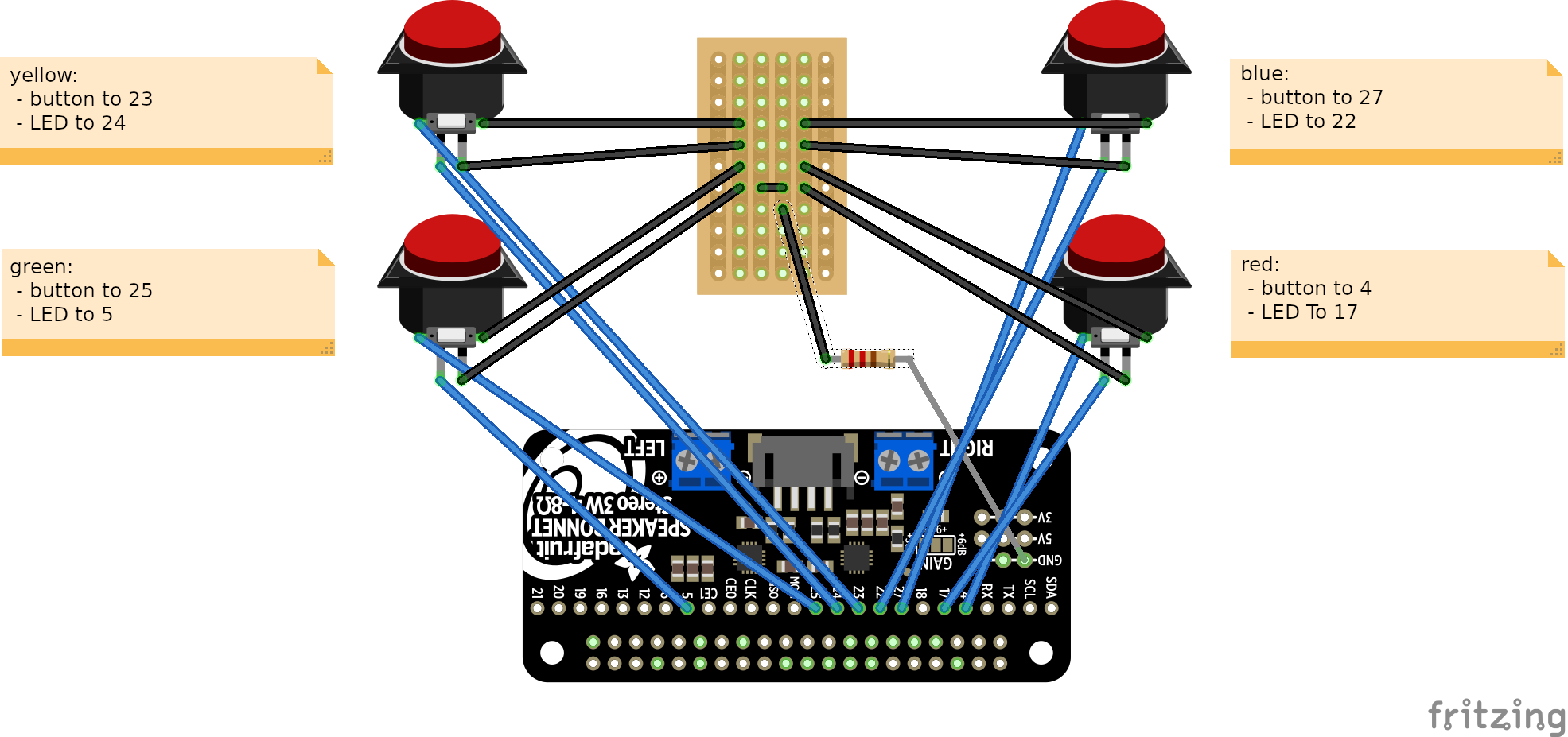
Connection Details & Diagram #
See below for more notes and reference images. The connections are made from the pushbuttons to the bonnet. The ground connections just need to go to ground using a 220 to 1000 Ohm resistor - the details are not important. If you want to be extra careful on the wiring or are making any modifications to the code/purpose, you can see the code section to verify what LEDs/buttons are connected to what GPIO pins. I’ve also marked it in the image here for an easy reference. The orientation of this image is the same orientation as the images below. Looking at the box with the lid open.
Soldering Notes #
General soldering notes
- if you are not experienced, would advise you review Adafruit’s Guide To Excellent Soldering - maybe you can do better than I did!
- if you make a mess with solder, use the solder wick to clean it up. You can find resources online on how to properly use solder wick.
In this minimal version, I am not screwing down or glueing the Pi down to the enclosure. Some notes:
- I did cut the protoboard to a reasonable size, you can use scissors or utility knife for this
- before you begin soldering, do a quick double check to ensure that with the pushbuttons, Pi + bonnet + speaker, in the enclosure, you can still open and close the box. This is to check your tab placement and general space.
- I used tape and some glue to reinforce the holes for the pushbuttons to ensure that the paper won’t tear or bend, this will be much easier to do before soldering if you want to reinforce the holes.
- remember, you are soldering near paper, not metal. Be careful. Don’t let the soldering gun touch the paper. It will burn. Do not let children solder unsupervised.
- I would reccomend you focus on relying on your understanding of how the pushbutton works, and the fritzing diagram connections you are making as a guide, rather than trying to copy the image. The wires are a bit hard to see in the image.
- place the buttons through the holes and screw them in with the plastic circular nut before you solder.
- you will need to do a fair bit of tinkering, ensure that you can lay down the box flat with the lid open and have enough wire length to reach the buttons. Use a bit more wire length rather than not enough
- I’d reccomend to solder all the positive leads to the respective GPIO pins, then focus on the ground pins once that looks neat. The ground pins will be easier since we’re using protoboard. The ground pins don’t need to be arranged in any particular way, the important thing is that they all go to ground on the Pi.
- even after its all connected, you’ll want to have some wiggle room for the Pi to move around a bit inside the enclosure - remember, you want to be able to connect power and other peripherals to the exposed ports.
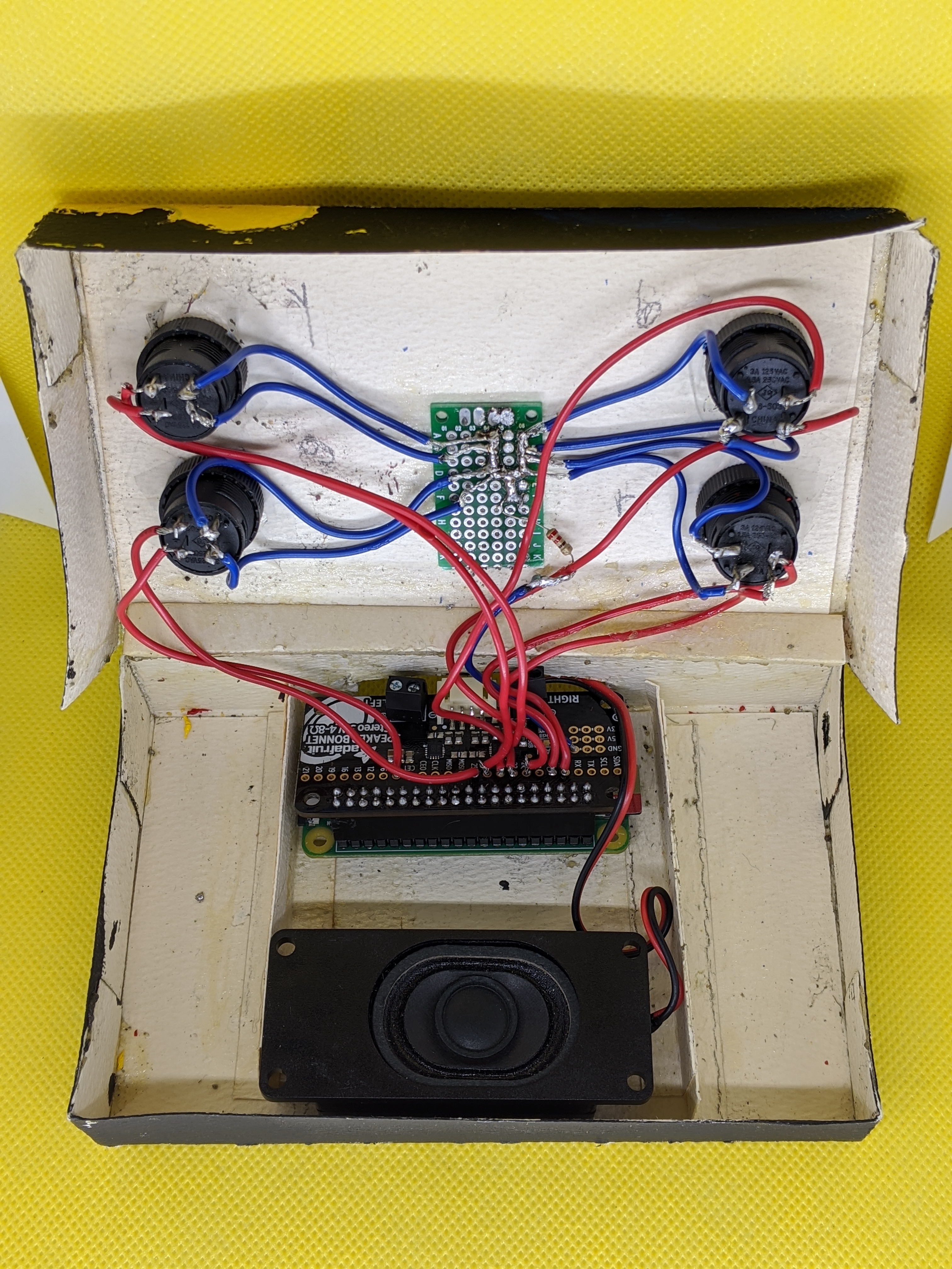
- Reference below is just to show that I soldered on the underside of the speaker bonnet and it definitely isn’t pretty but its worked solidly and survived for over 2 years! This is just to give you an idea of how I did it.
Code #
quick setup instructions #
I’d suggest you make sure you are in the home directory before you proceed to make things simpler
# cd /home/pi/
In order to download the code from this repository, you’ll need to run:
# git pull https://github.com/theodore-dream/audio-emotion-toy
Then, you will need to move the AudioClips directory to the location referenced in the code
# mv AudioClips /home/pi/Documents/
Make sure the python script is executable and go ahead and put it in AudioClips directory
# mv audio-emotion-toy.py /home/pi/Documents/AudioClips/
# sudo chmod +x /home/pi/Documents/AudioClips/audio-emotion-toy.py
Now we’ll setup a cronjob on reboot using crontab so that the script will run automatically on reboot
# sudo crontab -e

[place this line at the bottom and make sure its pointing to the file location where the script is]
@reboot sleep 10 && sudo python  /home/pi/Documents/AudioClips/audio-emotion-toy.py
Ensure that cron service is enabled
sudo systemctl enable cron
Then reboot and wait a few moments and try pressing a button! If it works, you’re done!
brief overview of the code for educational purposes #
This first part imports python modules. Most of these are commonly seen in button/led Pi examples, however the use of “sys” is unique here so we can access the audio files. Note the bottom two lines is where I setup GPIO use and set BCM mode GPIO. If you used a different GPIO scheme, you’d need to change it there.
#!/usr/bin/env python
import os, random
import sys
import time
from time import sleep

import RPi.GPIO as GPIO
GPIO.setmode(GPIO.BCM)
Here I setup all of the GPIO pins and correspond them to each color and emotion. The top line sets the button and the bottom line sets the GPIO as an output to send power for the LEDs.
GPIO.setup(4, GPIO.IN, pull_up_down=GPIO.PUD_UP) #RED B = ANGER
GPIO.setup(17, GPIO.OUT) #RED L = ANGER

GPIO.setup(27, GPIO.IN, pull_up_down=GPIO.PUD_UP) #BLUE B = SADNESS
GPIO.setup(22, GPIO.OUT) #BLUE L = SADNESS

GPIO.setup(23, GPIO.IN, pull_up_down=GPIO.PUD_UP) #YELLOW B = JOY
GPIO.setup(24, GPIO.OUT) #YELLOW L = JOY

GPIO.setup(25, GPIO.IN, pull_up_down=GPIO.PUD_UP) #GREEN B = FEAR
GPIO.setup(5, GPIO.OUT) #GREEN L = FEAR
Here I create each of the functions. What it does first it specifies the button action. For example, when the red button is pressed [we haven’t gotten there yet] the GPIO 17 will be powered for the red LED. Then I specify a random file from the Anger directory, and I make sure to add the entire file path to set the specific filepath for “file” variable to the full filepath, plus the randomfile that I’ve let python decide for me. Then I use “os.system” to run a command to use mpg123 to run the file. Then wait half a second and power down GPIO 17 to turn the red LED back off.
def rndanger (): #RED
	GPIO.output(17, GPIO.HIGH)
        randomfile = random.choice(os.listdir("/home/pi/Documents/AudioClips/ANGER"))
        file = '/home/pi/Documents/AudioClips/ANGER/' + randomfile
        os.system('mpg123 ' + file)
	sleep(0.5)
	GPIO.output(17, GPIO.LOW)

def rndsadness (): #BLUE
	GPIO.output(22, GPIO.HIGH)
	randomfile = random.choice(os.listdir("/home/pi/Documents/AudioClips/SADNESS/"))
	file = '/home/pi/Documents/AudioClips/SADNESS/' + randomfile
	os.system ('mpg123 ' + file)
        sleep(0.5)
        GPIO.output(22, GPIO.LOW)

def rndhappiness (): #YELLOW
	GPIO.output(24, GPIO.HIGH)
	randomfile = random.choice(os.listdir("/home/pi/Documents/AudioClips/HAPPINESS/"))
	file = '/home/pi/Documents/AudioClips/HAPPINESS/' + randomfile
	os.system ('mpg123 ' + file)
        sleep(0.5)
        GPIO.output(24, GPIO.LOW)

def rndfear (): #GREEN
	GPIO.output(5, GPIO.HIGH)
        randomfile = random.choice(os.listdir("/home/pi/Documents/AudioClips/FEAR/"))
        file = '/home/pi/Documents/AudioClips/FEAR/' + randomfile
        os.system ('mpg123 ' + file)
        sleep(0.5)
        GPIO.output(5, GPIO.LOW)
We have reached the main loop. The endless while loop, simply states that if the corresponding button press is detected on the button GPIO, to run the respective function that we’ve set above, to play the clip and light the LED.
while True:
	if (GPIO.input(4) == False): #RED/ANGER
                rndanger ()
                sleep(0.1)

	if (GPIO.input(27) == False): #BLUE/SADNESS
		rndsadness ()
		sleep(0.1)

        if (GPIO.input(23) == False): #YELLOW/HAPPINESS
                rndhappiness ()
                sleep(0.1)

	if (GPIO.input(25) == False): #GREEN/FEAR
		rndfear ()
		sleep(0.1)
Thank you for reading.